
Introduction:
The LM7 4 Pin to 1 Cable Alternator Wiring Diagram is the guide when wiring an alternator. Now, let’s look at the wiring system of an alternator. Since it can get a little complex, we will take it step by step. In this guide, you will be enlightened on the role of the LM7 alternator, how to read its wiring diagram and its functioning. No, let me explain in detail the 1 Cable Alternator Wiring Diagram. in detail
What is an LM7 Alternator?
The LM7 alternator is a 145-amp model meant only for vehicles with a certain electrical system. The later version of the LM7 used an alternator with a signal wire and one main power wire. This design is imperative for achieving the efficiency of the alternator and all the electrical components of a vehicle.
The Purpose of the LM7 Alternator
The LM7 4 Pin to 1 Cable Alternator Wiring Diagram controls the voltage from the alternator. This assists in seeing that the vehicle’s battery is always charged. Moreover, it supplies the electrical needs of the vehicle and its interior. The alternator is another important part of the vehicle’s power train.
Analyzing the Wires of the LM7 Alternator
The LM7 alternator has the following few main wires: essential system components. Now let’s consider the wires engaged;
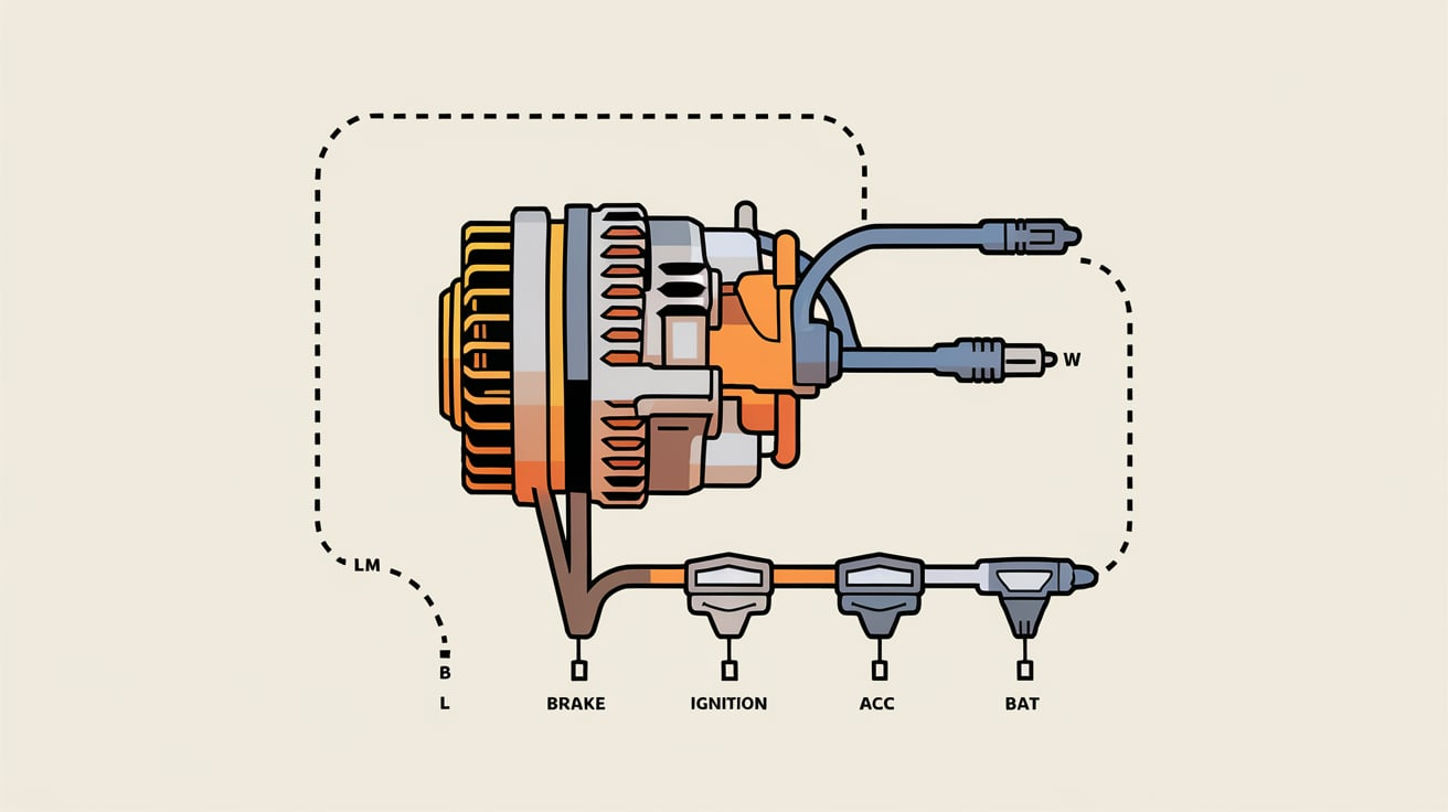
Brown Wire – Charge Indicator Control
In the LM7 4 Pin to 1 Cable Alternator Wiring Diagram, the brown wire controls the charge indicator and connects to the vehicle’s dashboard. When the alternator is good, it sends a signal that the battery is being recharged. If there is a problem, the charge indicator light will be on the dashboard.
The engineer enables this scrumptious gray wire, which provides the generator field duty cycle signal.
Any car enthusiast should know about the gray wire, another important part of the LM7 4 Pin to 1 Cable Alternator Wiring Diagram. It is for the generator duty cycle signal of the field. This wire plays an important role in regulating the current of this alternator’s field. The alternator regulates the field current, which in turn allows the amount of voltage to be generated to be controlled.
The Importance of Proper Wiring
Ordinary wiring cannot be compromised on any alternator, and this is not exempted from the LM7 4 Pin to 1 Cable Alternator Wiring Diagram. Several problems that may arise due to improper wiring include the following: For instance, the alternator will not be able to charge the battery as required. Or we can have situations where electrical-related elements in the car do not function as expected.
If the wiring is done wrongly, it can also harm the alternator. At other times, it can lead to overheating of the alternator. This may result in additional wear or even a breakdown of the alternator throughout the use and charging of an automobile.
Common Issues in Alternator Wiring
There are situations when the wiring to the alternator is problematic. These problems should be resolved as they mess up the vehicle’s overall performance. Here are some examples of the issues associated with the LM7 4 Pin to 1 Cable Alternator Wiring Diagram.
Loose Connections
One of the many types of wiring problems is loose connections. When wiring is loosely connected, several electrical issues may occur. For instance, the alternator may not charge the battery as it should addition, all links should be tightly screwed and firmly tightened.
Broken or Frayed Wires
Losing care oneostt care connections are the most frequent problem, such as broken or separated wires. However, wires deteriorate with time, and other forces can damage them in different ways. This can remove the capacity of the alternator to get correct signals. This is because damaged wires are a potential threat to other related circuitry and should be replaced soon.
Faulty Wiring Diagram
Sometimes, the LM7 4 Pin to 1 Cable Alternator Wiring Diagram may not be obeyed in the correct manner. This can cause problems such as incorrect wiring of the entire circuit, which is not good for the alternator. The proper wiring diagram must always be used when carrying out the installation.
How to Wire the LM7 Alternator
Many variations exist in the alternator wiring diagrams, starting with the LM7 4 Pin to 1 Cable Alternator Wiring Diagram. Here is the alternator’s wire. Then, the following are the basic steps to follow.
Step 1: Disconnect the Battery
Never begin any electrical activities to reduce danger without removing the vehicle’s battery. This will help avoid any kind of current electrical shock or shutdown of the system.
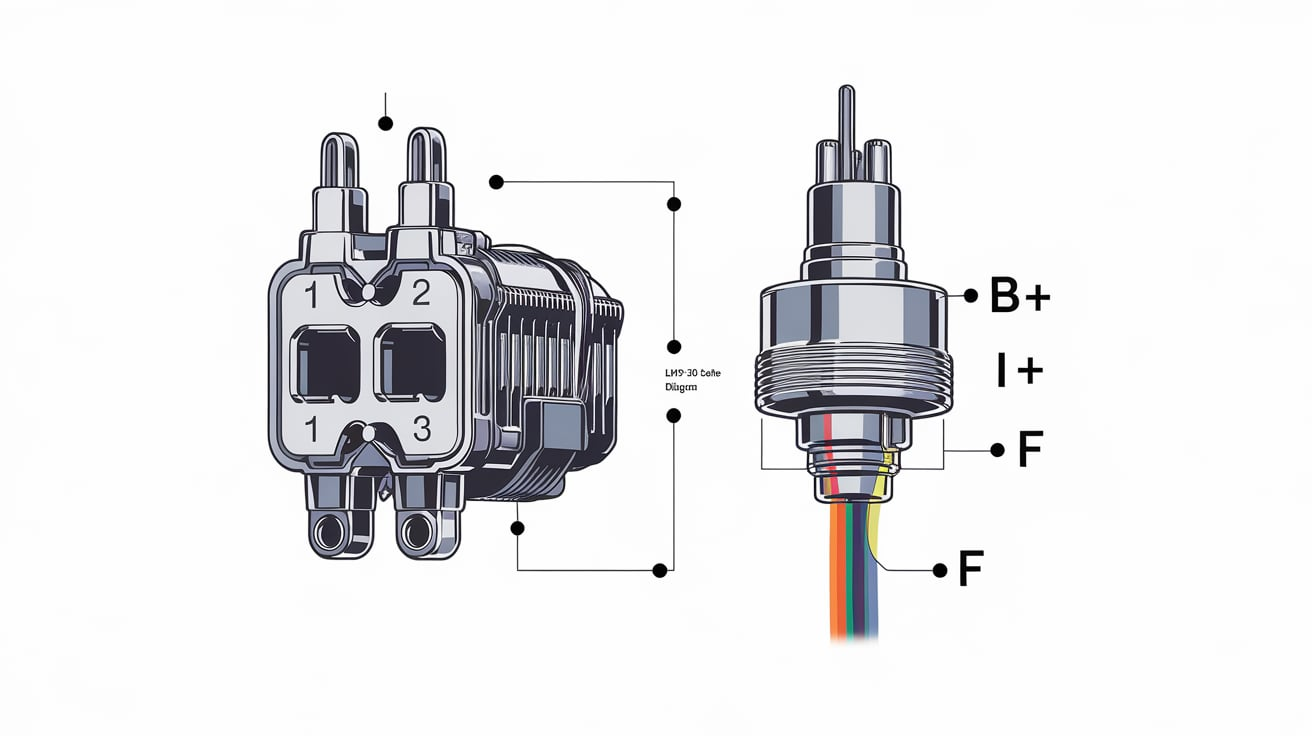
Step 2: Identify the Wires
After that, locate the brown and gray wires after the battery has been disconnected. The brown wire is for the charge indicator control, and you and your generator’s field duty cycle signal are on the gray wire.
Creep 3: Connect the Wires
Third, plug the brown wire into the charge indicator on the dashboard’s side. After that, the gray wire is soldered to the field control circuit of the alternator. This has to be ensured that all the connections with the security are made and locked correctly.
Step 4: Attach the cable. Finally, one connects the alternator cable to the vehicle’s electrical power and the wire is connected. The cable should be connected to the positive terminal of the alternator.
Step 5: Test the System
After all wiring has been done, connect back the vehicle’s battery as mentioned by the manufacturer. After that, start the engine and look for the charge light on the dashboard. If all connections have been correctly established, the light should be off. If it comes on, then there may be a problem with the wiring.
Why You Need the LM7 4 Pin to 1 Cable Alternator Wiring Diagram
The LM7 4 Pin to 1 Cable Alternator Wiring Diagram is helpful to anybody with a car servicing their vehicle and needs to rewire the electrical connections of the car. Without this diagram, the wiring regarding the alternator can often go wrong in one way or another. This is very easy, especially when understanding how the alternator should be widely read.
Benefits of Using the Wiring Diagram
The proper wiring diagram will guarantee the alternator’s proper functioning. This assists in keeping the vehicle’s battery charged and guarantees the electrical installation’s effective working. It also eliminates situations where an operation could damage the alternator or other parts of the electrical framework.
Conclusion
This LM7 4 Pin to 1 Cable Alternator Wiring Diagram is essential to those struggling with the LM7 alternator. This way, one can confirm whether the alternator is correct to perform to the maximum. To maintain the proper functioning of the electrical system, one should ensure proper wiring of the vehicle. This implies that the various wires have the following meanings: brown wire – charge indicator control, gray wire – generator field duty cycle signals, and thus, the alternator installation becomes a forest.
Just a quick reminder: proper wiring is crucial for an alternator’s correct operation. A wrong connection can cause problems such as poor battery recharging or electrical system malfunction. Stick to the LM7 4 Pin to 1 Cable Alternator Wiring Diagram to avoid these issues when installing the alternator.
With the proper measures of approach, knowledge of the wiring system, and the correct wiring diagram, you can be assured that your alternator will operate at full blast and your vehicle will be powered.